CH3: Storage Fundamentals, Slack Space, and Formatting
Introduction
Every finding you report in a data recovery case eventually rests on arithmetic. A file size is a four-byte value read in the correct order. A cluster size is a sector count multiplied by a sector size. A block of recoverable text sits in the gap between where a file's data ends and where its last cluster ends. Forensic tools do this arithmetic for you, and they are usually right. When a tool is wrong, or when opposing counsel asks how you know it was right, you have to be able to do the arithmetic yourself.
This chapter builds that foundation in three layers. First, you learn to read raw bytes: binary, decimal, and hexadecimal, plus the byte-ordering convention that decides whether an exfiltrated file was 4 KB or 1 MB. Second, you learn the physical and logical geometry of storage: sectors, clusters, volumes, and the slack space that appears wherever a file does not fill its last cluster. Third, you learn what formatting actually removes, which determines how much of that geometry still holds recoverable evidence when a drive arrives with the custodian claiming they wiped it.
None of this requires a partition table. Chapter 4 takes up boot firmware, MBR, GPT, and hidden storage areas, and it assumes you can do everything in this chapter without reaching for a calculator. The roles that depend on this material most directly are digital forensic technician, e-discovery analyst, and incident response analyst, all of which are expected to validate tool output rather than repeat it.
Learning Objectives
By the end of this chapter, you will be able to:
- Convert values between binary, decimal, and hexadecimal, and read multi-byte values in the correct endian order.
- Describe the relationship between bits, nibbles, bytes, words, DWORDs, and QWORDs as they appear in a hex editor.
- Verify a drive's logical and physical sector size using platform tools before performing any offset calculation.
- Calculate cluster size, total file slack, RAM slack, and drive slack from sector size, sectors per cluster, and file size.
- Distinguish logical drives from physical drives, and logical files from physical files.
- Predict what a quick format and a full format leave recoverable on FAT and NTFS volumes.
3.1 Working in Hex: The Examiner's Native Language
A hex editor is to a forensic examiner what a microscope is to a biologist. It strips away abstractions and shows you the actual bytes on disk. Every partition boundary, every filesystem signature, every hidden value is encoded in hexadecimal. You need fluency in hex work not because it is elegant, but because it is the only way to verify what tools claim to find.
Why Hexadecimal?
Storage media stores data as bits: 0 or 1. Humans cannot process streams of individual bits efficiently. Hexadecimal (base 16) compresses binary into a readable form: every 4 bits become a single hex digit (0-F), and every 2 hex digits represent one byte. A single byte of data like 11010110 in binary becomes D6 in hex. In a hex editor, you see the data in two views simultaneously: the hex values on the left, the ASCII representation (where applicable) on the right.
Analyst Perspective
Open any forensic image in a hex editor like HxD or xxd. The first 512 bytes are the Master Boot Record. The last two bytes of that sector, at offsets 510 and 511, are almost always 55 AA. Read as a little-endian 16-bit word, those two bytes are the value 0xAA55, the MBR signature. You will see this same pattern on millions of drives. When you see something different, you know something is wrong: corruption, encryption, or an intentional modification that may itself be evidence.
Number System Conversion
Forensic work demands fluency moving between decimal, hexadecimal, and binary. Consider a timestamp or a file size stored in a directory entry: it is encoded in hex, but you need to convert it to decimal to understand its meaning in human time or in bytes.
Understanding Number Bases
A number base (or radix) defines how many unique digits are available in a numbering system. Each digit position represents a power of that base:
- Binary (base 2): Uses 2 digits (0 and 1). Each position represents a power of 2. Binary 1101 = (1 × 2³) + (1 × 2²) + (0 × 2¹) + (1 × 2⁰) = 8 + 4 + 0 + 1 = 13 decimal.
- Decimal (base 10): Uses 10 digits (0–9). Each position represents a power of 10. Decimal 214 = (2 × 10²) + (1 × 10¹) + (4 × 10⁰) = 200 + 10 + 4.
- Hexadecimal (base 16): Uses 16 digits (0–9 and A–F, where A=10, B=11, C=12, D=13, E=14, F=15). Each position represents a power of 16. Hex D6 = (D × 16¹) + (6 × 16⁰) = (13 × 16) + (6 × 1) = 208 + 6 = 214 decimal.
The same value, 214, looks different in each base: 11010110 in binary, 214 in decimal, and D6 in hexadecimal. The value is identical. Only the representation changes.
Binary to Decimal
Each bit position represents a power of 2. Position 0 (rightmost) = 2^0 = 1. Position 1 = 2^1 = 2. Position 2 = 2^2 = 4. And so on.
Binary 11010110 breaks down as:
- 1 at position 7: 1 × 128 = 128
- 1 at position 6: 1 × 64 = 64
- 0 at position 5: 0 × 32 = 0
- 1 at position 4: 1 × 16 = 16
- 0 at position 3: 0 × 8 = 0
- 1 at position 2: 1 × 4 = 4
- 1 at position 1: 1 × 2 = 2
- 0 at position 0: 0 × 1 = 0
Sum: 128 + 64 + 16 + 4 + 2 = 214 decimal. Figure 3.1 lays out the same conversion by bit position.
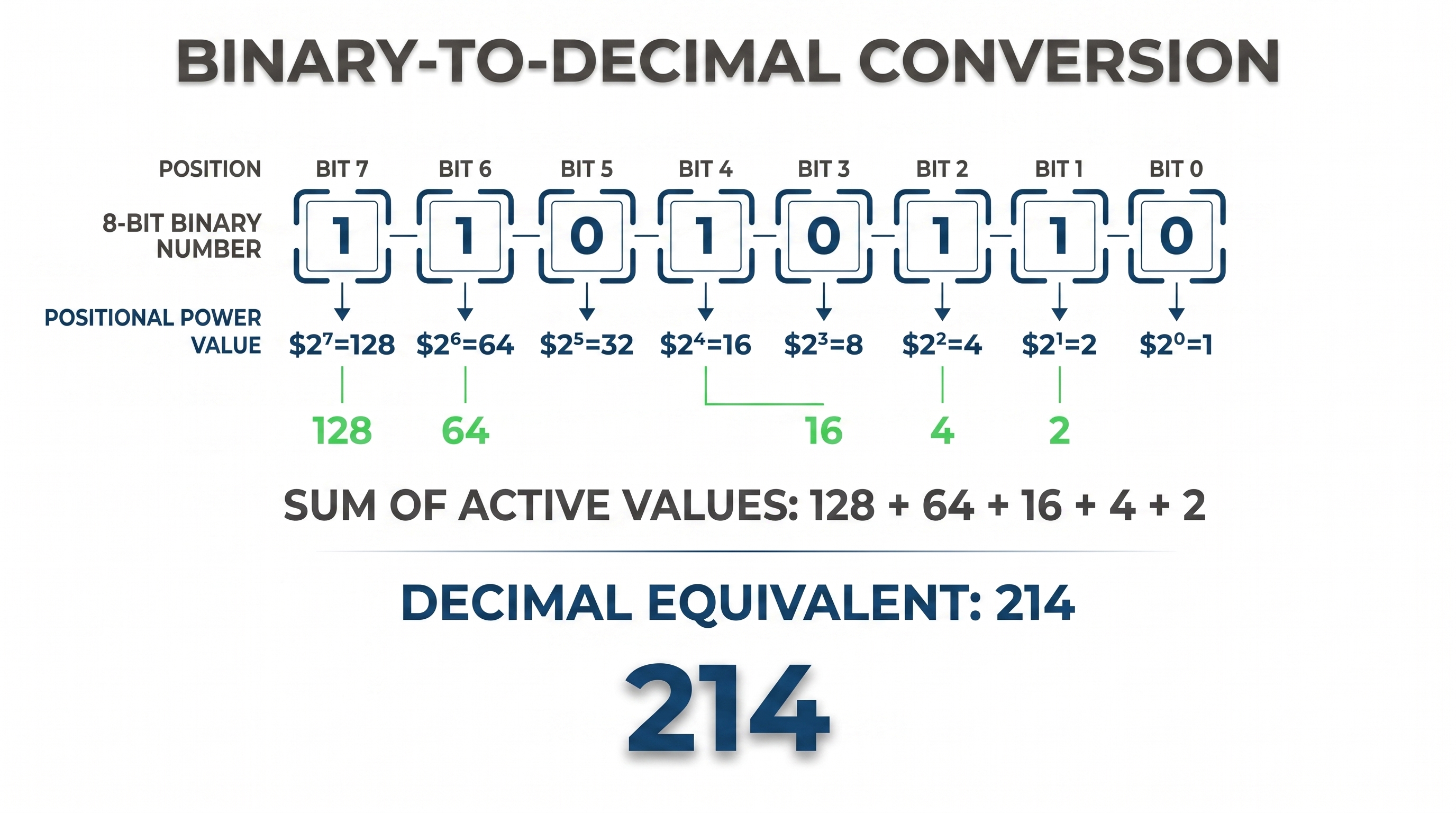
Figure 3.1: Positional conversion of binary 11010110 to decimal 214. Only the positions holding a 1 contribute, so the sum is 128 + 64 + 16 + 4 + 2.
Nibbles and Hex Bytes
A nibble is 4 bits, or half a byte. Because hexadecimal uses 16 digits (0–F), each hex digit represents exactly one nibble. A single hex byte (2 hex digits) represents 8 bits: the high nibble (leftmost hex digit) represents bits 7–4, and the low nibble (rightmost hex digit) represents bits 3–0.
For example, hex D6 breaks into two nibbles:
- High nibble: D = 1101 binary
- Low nibble: 6 = 0110 binary
- Combined: 11010110 binary = 214 decimal
This one-to-one mapping between a hex digit and a group of 4 bits is why hex notation is used throughout forensics. Conversion between hex and binary needs no intermediate step.
Quick Reference: Hex Digit Values
| Decimal | Hex | Binary | Decimal | Hex | Binary |
|---|---|---|---|---|---|
| 0 | 0 | 0000 | 8 | 8 | 1000 |
| 1 | 1 | 0001 | 9 | 9 | 1001 |
| 2 | 2 | 0010 | 10 | A | 1010 |
| 3 | 3 | 0011 | 11 | B | 1011 |
| 4 | 4 | 0100 | 12 | C | 1100 |
| 5 | 5 | 0101 | 13 | D | 1101 |
| 6 | 6 | 0110 | 14 | E | 1110 |
| 7 | 7 | 0111 | 15 | F | 1111 |
Hexadecimal to Decimal
Each hex digit position represents a power of 16. To convert hex D6 to decimal, you can work with hex digits directly or break them into nibbles (4-bit binary) for added insight:
Hex digit method: (D × 16^1) + (6 × 16^0) = (13 × 16) + (6 × 1) = 208 + 6 = 214 decimal.
Nibble method: Convert each hex digit to its 4-bit binary nibble, combine them, and convert the resulting 8-bit value to decimal:
- D hex = 1101 binary (high nibble)
- 6 hex = 0110 binary (low nibble)
- Combined: 11010110 binary = 128 + 64 + 16 + 4 + 2 = 214 decimal
Both methods yield 214 decimal. The nibble method reinforces the connection between hex, binary, and decimal representations, as traced in Figure 3.2.
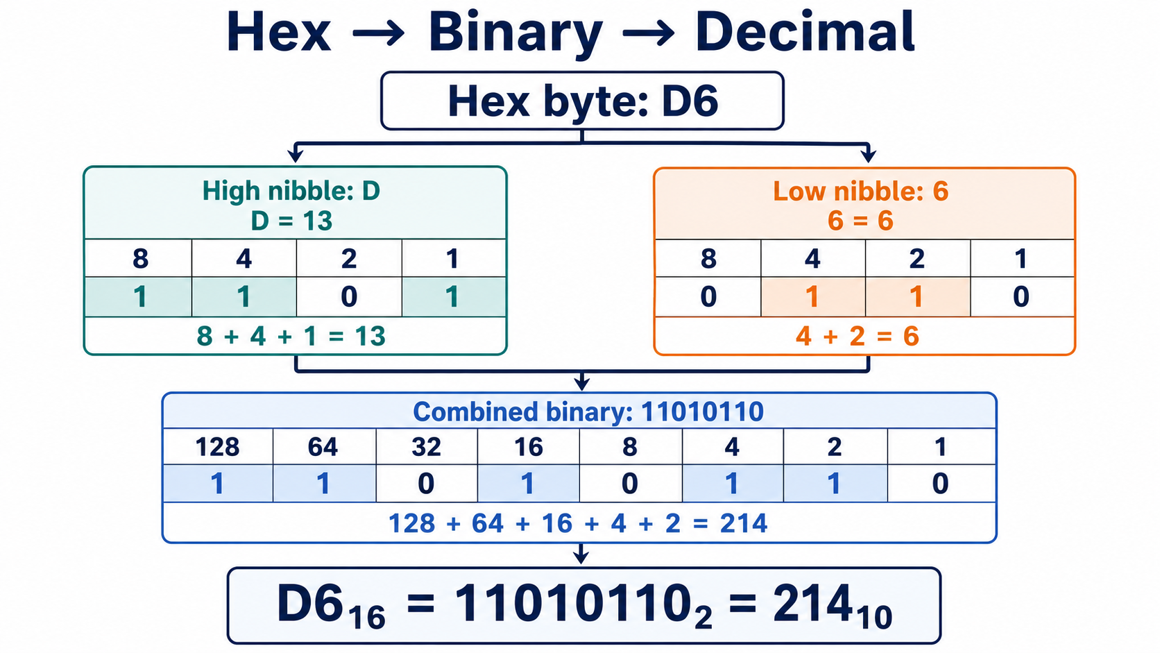
Figure 3.2: One byte in three representations. Hex D6 splits into the nibbles D and 6, which expand to 1101 and 0110, giving the 8-bit value 11010110, or 214 decimal.
Bytes, Words, and Endianness
Storage conventions name larger units of data. A byte is 8 bits. A word is 2 bytes (16 bits). A double-word (DWORD) is 4 bytes (32 bits). A quad-word (QWORD) is 8 bytes (64 bits).
Endianness describes the order in which multi-byte values are stored in memory or on disk.
- Little-endian systems (Intel x86, ARM) store the least significant byte first. You reverse the bytes you see in the hex editor to recover the value.
- Big-endian systems (Motorola, network protocols) store the most significant byte first. You read the bytes in the order they appear.
Consider the 4-byte value 0x12345678 (hexadecimal). In a hex editor:
- Little-endian storage shows: 78 56 34 12.
- Big-endian storage shows: 12 34 56 78.
Figure 3.3 shows both storage orders side by side at the same four addresses.
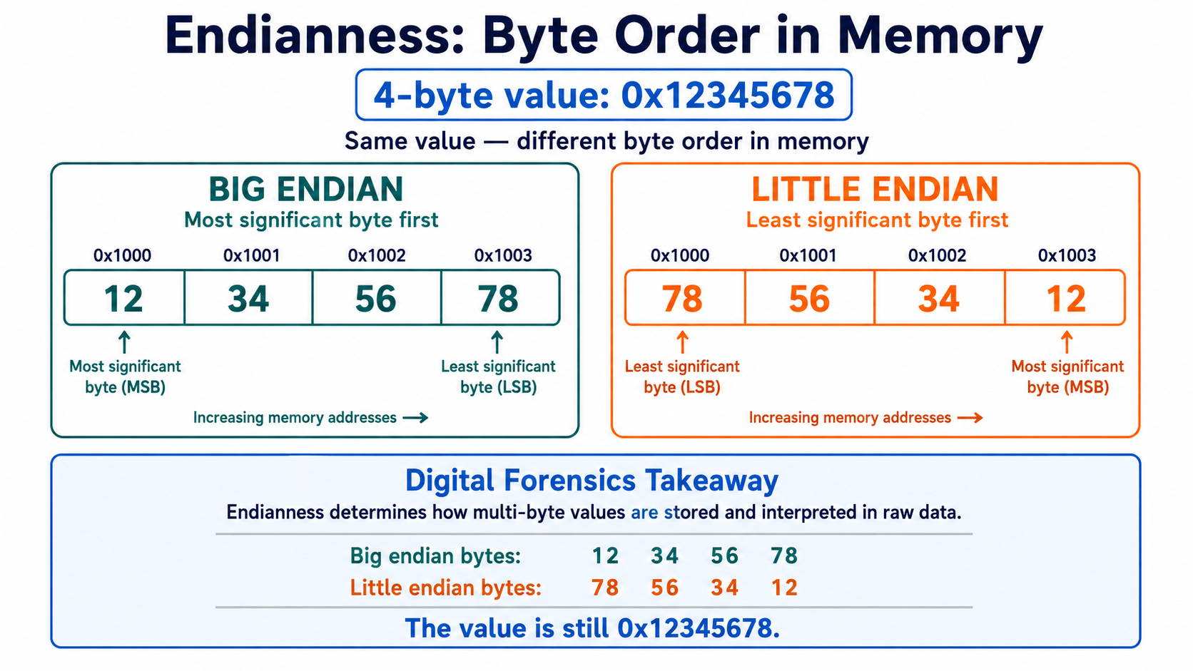
Figure 3.3: The value 0x12345678 stored big-endian and little-endian. The bytes on disk differ while the value they encode does not, which is why byte order has to be established before any multi-byte field is interpreted.
Real-World Example: Endianness and Investigative Error
Consider a USB drive acquisition where you discover evidence of data exfiltration. In a FAT32 directory entry, you find a file size stored as hex bytes: 00 10 00 00 (little-endian).
Correct interpretation (accounting for little-endian order):
- Reverse the byte order: 0x00001000 = 4,096 bytes
- Conclusion: A small 4 KB file was transferred. Likely a text document or small spreadsheet.
Incorrect interpretation (treating it as big-endian):
- Read the bytes left to right without reversing: 0x00100000 = 1,048,576 bytes (1 MB)
- Conclusion: A 1 MB file was transferred. Possibly a database, archive, or media file.
Investigative consequence: Misreading endianness makes the exfiltrated data appear 256 times larger than it actually was. This error could change:
- The severity assessment of the data theft
- The suspect's apparent motive and culpability
- The scope of the breach
- Potential charges (small document theft versus large database theft)
Timestamp fields stored in little-endian order are vulnerable to the same mistake, which can place critical events on entirely wrong dates or times.
Forensic practice: Always cross-check interpreted values against known patterns. If a file size seems implausibly large, or a timestamp falls outside the device's operational lifetime, verify the byte order before drawing conclusions.
Hex Editor Orientation
Opening a forensic image in a hex editor shows an offset column (leftmost), hex bytes (center), and ASCII representation (right). The offset column shows the byte position from the start of the image, expressed in hex.
Byte offsets are zero-indexed. Offset 0x00000000 is the first byte of the image. Offset 0x000001FF is decimal 511, the last byte of the first 512-byte sector. Offset 0x00000200 is decimal 512, the first byte of the second sector.
When reading a partition table entry that spans offsets 446 through 509 in the MBR, you navigate to offset 0x1BE (446 decimal) and read 64 consecutive bytes. Each entry within that block occupies a specific byte range. Precision matters.
Figure 3.4 shows this layout in HxD, with the end of the first sector highlighted.
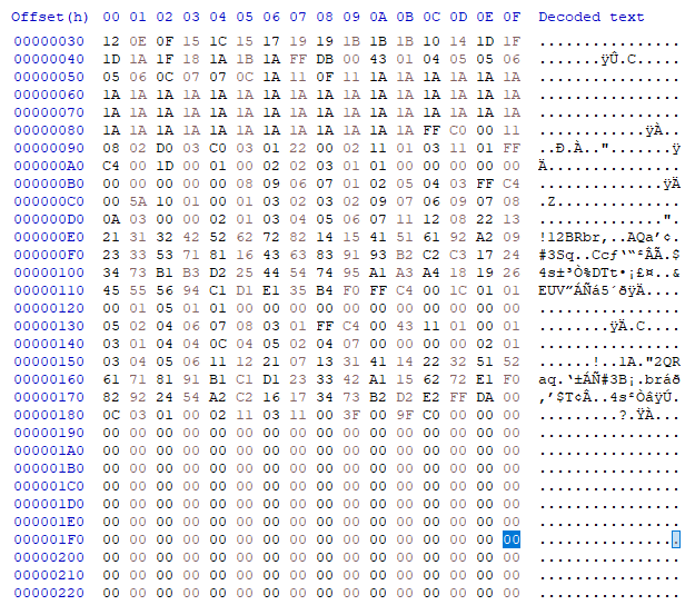
Figure 3.4: The three-pane hex editor layout in HxD. Offsets run down the left in hexadecimal, 16 bytes render per row in the center, and the ASCII interpretation runs down the right. The highlighted offset 0x000001FF is decimal byte 511, the last byte of the first sector.
Each row of the center pane represents 16 bytes, so a 512-byte sector spans exactly 32 rows. The offset immediately after the highlight, 0x00000200, is decimal byte 512 and begins the second sector. You will use this layout constantly when locating partition boundaries, boot records, and filesystem structures. HxD is free, runs on Windows, and is a common choice in forensic labs.
3.2 Physical Storage Geometry
A hard disk drive stores data in concentric circular tracks. A solid-state drive (SSD) stores data in a grid of cells. Both present themselves to the operating system as a linear sequence of sectors, numbered from 0 onward. Sector and cluster organization is the foundation for calculating file slack, locating volume boundaries, and recovering fragmented files.
Sectors and Sector Sizes
A sector is the smallest addressable unit of storage. For decades, the standard sector size was 512 bytes. In the 2000s, manufacturers began moving to 4,096-byte (4 KB) sectors under a standard called Advanced Format (AF). Some very large drives now use 4 KB sectors exclusively. Others support both modes through 512-byte emulation, reporting a 512-byte logical sector size while using 4 KB physical sectors internally.
Storage structures reference sectors by number, not by byte offset. A partition entry might state "starting sector 2048." That means the partition starts at byte offset 2048 × 512 = 1,048,576, assuming 512-byte sectors. If the drive actually uses 4 KB sectors, the same entry value produces a different byte offset: 2048 × 4096 = 8,388,608. A sector-size mismatch pushes every calculated boundary off by a factor of eight, producing a cluster map that is either far too large or far too small.
Verifying Sector Size: A Best Practice
Before calculating byte offsets or parsing on-disk structures, always verify the actual sector size of the target drive. Tools sometimes assume 512-byte sectors by default and produce nonsensical results on Advanced Format drives when the sector size is not corrected.
On Linux:
Use hdparm to query drive properties. The -I flag displays detailed information:
hdparm -I /dev/sdX | grep "Sector size"
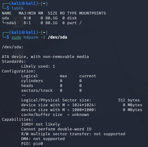
Figure 3.5: hdparm -I output on a Linux system. The drive reports a logical and physical sector size of 512 bytes. On an Advanced Format drive these two values differ, and the difference is what tools most often get wrong.
On Windows:
Use PowerShell to query logical and physical sector sizes:
Get-PhysicalDisk | Select-Object FriendlyName, Size, LogicalSectorSize, PhysicalSectorSize
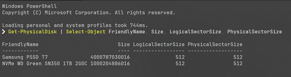
Figure 3.6: Get-PhysicalDisk output in PowerShell. Reporting both sector sizes for every attached device makes this a fast intake check when several drives are connected at once.
Or use fsutil to query a mounted NTFS volume, which also reports the cluster size:
fsutil fsinfo ntfsinfo C:
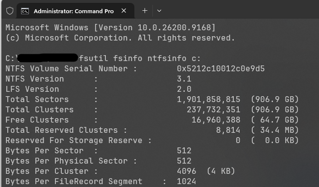
Figure 3.7: fsutil fsinfo ntfsinfo output. This command reports the cluster size (Bytes Per Cluster) alongside the sector sizes, which is the pair you need for every slack calculation in this chapter. It requires an elevated prompt and works only on a mounted NTFS volume.
The drive manufacturer's specification sheet for the exact model is the definitive source, and it does not depend on a tool reporting accurately. Record the sector size in your examination notes before you compute anything from it.
Clusters and Allocation Units
A cluster (also called an allocation unit) is the smallest unit of storage that a filesystem can allocate to a file. Clusters are built from one or more consecutive sectors. A filesystem using a 4 KB cluster size holds exactly 8 sectors per cluster when sectors are 512 bytes. Cluster sizes vary by filesystem and by the total volume size.
Cluster size is set when the volume is formatted. The boot sector of a volume records the sectors-per-cluster value. From that and the sector size, you calculate the cluster size in bytes:
Cluster size = sectors per cluster × sector size
FAT32 on a 32 GB USB drive commonly uses 16 KB clusters. NTFS on a 500 GB partition typically uses 4 KB clusters. The same filesystem can have different cluster sizes on different volumes, depending on how each was formatted, which is why you read the value from the volume rather than assuming it.
Figure 3.8 shows how two files of different sizes occupy clusters, and how much of each allocation goes unused.
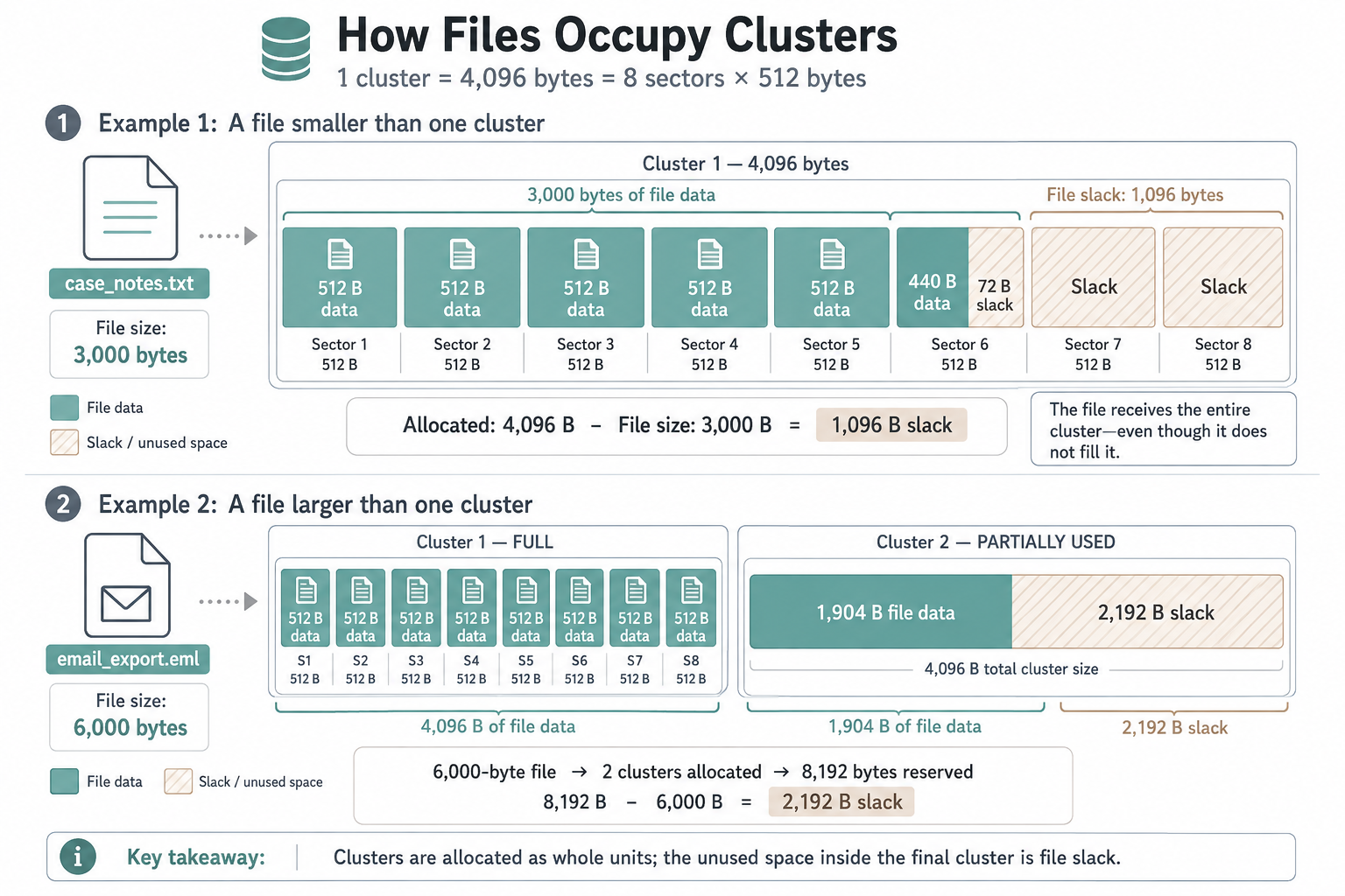
Figure 3.8: Two files in 4,096-byte clusters. A 3,000-byte file leaves 1,096 bytes of slack in its single cluster. A 6,000-byte file fills its first cluster and leaves 2,192 bytes of slack in its second. Only whole clusters are ever allocated, so the leftover always belongs to the file even though the file never wrote to it.
Volumes and Logical Drives
A volume is a formatted storage container that an operating system recognizes as a disk. It is defined by a start sector and a length in sectors. Multiple volumes can exist on a single physical drive, separated by partition boundaries.
Volumes are independent of one another. One may be NTFS, another FAT32, another ext4. One may be encrypted, another plain. One may be deleted with its sectors still holding data. The partition table tells the operating system which sectors belong to which volume. When a partition is deleted, that mapping is removed, but the data in those sectors persists until something overwrites it.
The partition table is itself data stored on the disk, at sector 0 for MBR and sector 1 for GPT. Chapter 4 covers how to locate that structure, parse it by hand, and detect storage that sits outside it.
File Slack and the Cluster Boundary
A file consumes space in whole clusters only. If a file is 100 bytes and the cluster size is 4,096 bytes, the file occupies one full cluster. The unused 3,996 bytes in that cluster become file slack.
Total file slack is calculated as:
File slack (bytes) = (cluster size - (file size mod cluster size)) mod cluster size
The outer mod cluster size handles one edge case. When a file size is an exact multiple of the cluster size, the inner subtraction returns a whole cluster, which is wrong. A file that fills its last cluster exactly has zero slack, and the outer operation returns 0 as it should. For every other file size, the outer operation changes nothing.
File slack has two components, and they come from different sources, which is why examiners report them separately.
RAM slack is the space between the end of the file data and the end of the last sector that holds file data. Suppose a file is 1,000 bytes on a volume with 512-byte sectors and 4,096-byte clusters. The file occupies one cluster. Its data fills sector 0 of that cluster (bytes 0 through 511) and part of sector 1 (bytes 512 through 999). Sector 1 ends at byte 1,023. RAM slack is bytes 1,000 through 1,023, or 24 bytes. Older operating systems padded this region with whatever happened to be in memory at the time of the write, which is where the name comes from. Modern Windows and Linux zero-fill it, but examiners still check, because the region can hold residue on older systems and on some embedded devices.
Drive slack is the space between the end of the last sector holding file data and the end of the cluster. In the example above, that is bytes 1,024 through 4,095, or 3,072 bytes. Those sectors were never written by the current file, so they still contain whatever the previous occupant of that cluster left behind. Drive slack is the more productive of the two for recovering deleted file fragments.
RAM slack plus drive slack equals total file slack. In the example: 24 + 3,072 = 3,096, which matches (4,096 - (1,000 mod 4,096)) mod 4,096 = (4,096 - 1,000) mod 4,096 = 3,096.
Logical vs. Physical Drives
The operating system presents volumes as logical drives: C:, D:, /dev/sdb1, and so on. Physically, all these volumes reside on one or more physical disks. A forensic image of a 2 TB drive is usually one image file representing the entire 2 TB as a linear sequence of sectors.
When analyzing that image, you identify volume boundaries, then extract or mount individual partitions as logical volumes. Tools such as Autopsy, FTK, and EnCase abstract this process, but you should understand what is happening underneath: the tool is reading the partition table, calculating byte offsets, and isolating each logical volume within the image.
The same distinction applies at the file level. A logical file is a regular file, a directory, or a symbolic link as recognized by the filesystem. A physical file is the actual cluster chain on disk that holds the file data. When a file is fragmented, the logical file (one named entity) spans multiple noncontiguous clusters, meaning multiple physical regions. File recovery often involves reconstructing the physical file from those scattered clusters.
3.3 Media Formatting and Its Forensic Impact
Formatting erases the logical connection between filenames and data. It does not necessarily erase the data itself. A quick format removes directory entries and allocation metadata but leaves the bulk of file data intact. A full format overwrites sectors with null bytes or a defined pattern.
Quick Format vs. Full Format
A quick format on FAT32 zeroes the File Allocation Table and the root directory but leaves file clusters untouched. When you quick-format a drive, the operating system resets the filesystem allocation structures while the old file data remains in the data area. Recovery tools scan for file signatures (magic bytes) to find and carve those files.
A full format overwrites the addressable sectors of the volume, destroying most recoverable data. Behavior varies by operating system version and filesystem, so verify rather than assume. On Windows Vista and later, a full format writes zeros to the entire volume. On SSDs, a format may trigger TRIM, which tells the flash controller the blocks are no longer in use. Once the controller garbage-collects those blocks, the data is unrecoverable through any host-level technique, including raw imaging.
Formatting Effects on FAT Volumes
Before formatting, a FAT32 volume has a Volume Boot Record (VBR), a FAT region (usually two copies), a root directory, and a data area.
After a quick format:
- The VBR is rewritten, producing a new volume serial number and updated timestamps.
- Both FAT copies are cleared, with all entries set to 0x00000000 (free).
- The root directory is cleared.
- The data area is untouched.
Forensic impact: every file appears deleted because the allocation metadata is gone, but signature-based carving recovers many of them intact. File slack in the data area still holds residue from the pre-format files.
Formatting Effects on NTFS Volumes
A full format on NTFS rewrites the Master File Table (MFT) and zeroes the addressable clusters of the volume. A quick format on NTFS rewrites the MFT and the volume metadata files but leaves the data area intact, so the recovery picture resembles the FAT case.
Forensic impact after a quick format: files whose data clusters have not been reallocated can often be recovered by carving or by parsing residual MFT records in unallocated space. Older deletions are harder to recover because newer files have overwritten those clusters.
Repartitioning Impact
Repartitioning a disk, including converting between MBR and GPT, does not by itself erase file data. If the new partition layout does not overlap the old one, the previous volume's data remains in what the operating system now treats as unallocated space. If repartitioning shrinks a partition, data beyond the new boundary becomes invisible to the operating system but is still readable through raw disk analysis. Chapter 4 covers how to find those regions.
Warning
When a custodian reports "I reformatted the drive," determine which format was performed, on which filesystem, on which operating system version, and on what media type. A quick format on a FAT32 flash drive leaves nearly everything recoverable. A full format on a Windows 11 NTFS volume leaves very little. A format that triggered TRIM on an SSD may leave nothing at all. Record the answers before you set expectations with the requesting party.
Putting It Together: Reading a Quick-Formatted Flash Drive by Hand
An employee at a regional engineering firm resigned on a Friday and returned a company 32 GB USB flash drive on Monday. IT noticed the drive was empty and escalated to you. The custodian states they "just reformatted it so the next person could use it." Counsel wants to know whether anything was on the drive, and whether the files were large enough to represent bulk design data.
Your acquisition is already complete. You have a verified raw image, usb-01.dd, and a write blocker log. Everything below is done in a hex editor on that image, with no filesystem tool involved, because your first job is to establish the geometry that every later tool result will depend on.
Step 1: Verify the sector size.
You query the source drive through the write blocker before imaging:
Get-PhysicalDisk | Select-Object FriendlyName, Size, LogicalSectorSize, PhysicalSectorSize
The drive reports a logical sector size of 512 bytes and a physical sector size of 512 bytes. You note this in the examination log. Every byte offset from here forward is a sector number multiplied by 512.
Step 2: Locate the volume boot record.
The volume begins at sector 2048, a standard alignment for removable media. Its first sector, the VBR, is therefore at:
2048 × 512 = 1,048,576 bytes, or offset 0x100000.
You navigate to 0x100000 in the hex editor. The first byte is 0xEB, an x86 short jump instruction, which is what a FAT boot sector begins with. The bytes at offsets 82 through 89 of that sector read 46 41 54 33 32 20 20 20, which is ASCII "FAT32 ". The volume is FAT32.
Step 3: Read the geometry out of the BPB.
The BIOS Parameter Block sits inside the VBR. Two fields matter right now, and both are read relative to the start of the VBR.
At VBR offset 11 (0x0B), a 2-byte little-endian value, bytes per sector:
00 02
Reverse the bytes: 0x0200 = 512 decimal. This confirms what the drive reported.
At VBR offset 13 (0x0D), a 1-byte value, sectors per cluster:
20
Hex 20 = 32 decimal. A single byte needs no endian handling.
Cluster size = 32 sectors × 512 bytes = 16,384 bytes (16 KB).
That 16 KB figure now governs every slack calculation for this volume.
Step 4: Confirm the format was a quick format.
You navigate to the start of the first FAT and find every entry beyond the two reserved entries set to 0x00000000. The root directory is likewise empty. You then jump into the data area and find it full of non-zero bytes, including recognizable file signatures. Cleared allocation structures over an intact data area is the FAT32 quick-format pattern described in section 3.3. A full format would have left the data area zeroed.
You report this as a factual observation: the allocation structures were reset and the data area was not overwritten.
Step 5: Carve a file and account for its slack.
Signature carving recovers a DOCX file. In an orphaned directory entry recovered from the data area, the 4-byte file size field at directory-entry offset 28 reads:
C4 54 00 00
Reverse for little-endian: 0x000054C4.
Convert: (5 × 16³) + (4 × 16²) + (12 × 16¹) + (4 × 16⁰) = 20,480 + 1,024 + 192 + 4 = 21,700 bytes.
Note what happens if you forget to reverse. Read as big-endian, C4 54 00 00 is 0xC4540000, or 3,293,839,360 bytes, roughly 3.07 GB. A 3 GB Word document does not exist. That implausibility is your cross-check, and it is the same error described in section 3.1.
Now the allocation. The file is 21,700 bytes and the cluster size is 16,384 bytes:
- Clusters required: 21,700 ÷ 16,384 = 1.32, rounded up to 2 clusters
- Space allocated: 2 × 16,384 = 32,768 bytes
- Total file slack: (16,384 - (21,700 mod 16,384)) mod 16,384 = (16,384 - 5,316) mod 16,384 = 11,068 bytes
Split that into its two components:
- File data ends at byte 21,700 of the allocation. Dividing by the 512-byte sector size, the last sector holding data is sector index 42 of the allocation, which spans bytes 21,504 through 22,015.
- RAM slack = 22,016 - 21,700 = 316 bytes
- Drive slack = 32,768 - 22,016 = 10,752 bytes, which is 21 whole sectors
- Check: 316 + 10,752 = 11,068, matching the total
Step 6: Examine the slack.
You read the 10,752 bytes of drive slack in the hex editor. Those 21 sectors were never written by the DOCX file, so anything in them predates it. The ASCII pane shows fragments of a comma-separated file with column headers matching the firm's parts inventory export. That content is evidence, and it came from a region no filesystem tool would have listed as containing a file.
What you can report.
The drive was quick-formatted rather than wiped. The data area was intact, and at least one document plus recoverable fragments of a second file were present. The recovered DOCX is 21,700 bytes, which is a normal document, not bulk design data. You can state the size with confidence because you read the field yourself, in the correct byte order, and you know the cluster geometry the value sits inside.
In practice, a digital forensic technician does this validation pass before handing results to an examiner or to counsel. The tool output and the hand calculation have to agree. When they do not, the hand calculation tells you which assumption the tool got wrong, and sector size is the assumption it gets wrong most often.
Chapter Summary
- Hex fluency is a working requirement. Converting between binary, decimal, and hexadecimal, and reversing little-endian byte order, is how you verify any value a tool reports.
- Endianness errors change case conclusions. A 4 KB file read in the wrong byte order becomes a 1 MB file. Cross-check every multi-byte value against what is plausible for the artifact.
- Sector size is the first thing you verify and the last thing you assume. Every byte offset in an examination is a sector number multiplied by the sector size, so an Advanced Format drive misread as 512-byte sectors puts every boundary in the wrong place.
- Clusters create slack, and slack holds evidence. Cluster size equals sectors per cluster times sector size. Total file slack is (cluster size - (file size mod cluster size)) mod cluster size, which correctly returns 0 for a file that fills its last cluster exactly. Drive slack is where fragments of earlier files survive.
- Logical and physical are different views of the same bytes. Logical drives and logical files are what the operating system names. Physical drives and physical cluster chains are what actually exists on the media.
- Formatting removes bookkeeping, not necessarily data. A quick format clears allocation structures and leaves the data area intact. A full format overwrites it. TRIM on an SSD can make recovery impossible regardless of the format type.
Chapter 4 moves from the geometry of a single volume to how the whole disk is divided. You will work through the BIOS and UEFI boot sequences, parse MBR and GPT structures by hand from raw hex, and locate storage that the operating system never reports at all, including Host Protected Areas and Device Configuration Overlays. Every calculation in that chapter uses the sector arithmetic you practiced here.